Download
-
Ledge STL
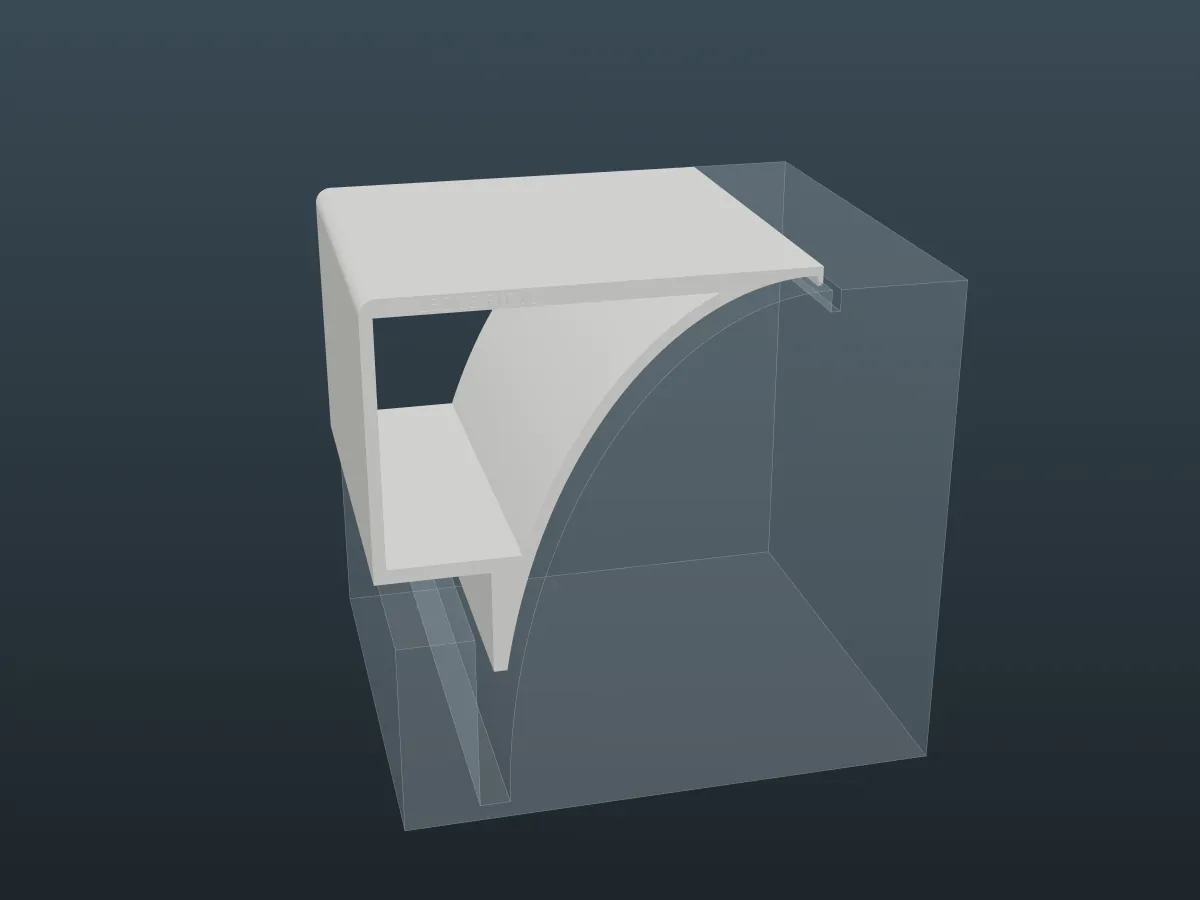
100 mm wide, 107 KB. Prints standing on its end in 2 h 13 min, with 80 g of PLA and no supports.
-
Fit test STL
4 mm wide, 93 KB. Prints flat in 16 min, with 4.3 g of PLA. Print this one first.
Times are Bambu Studio's, for a Bambu Lab A1 mini with a 0.4 mm nozzle and 0.20 mm layers.
What it fixes
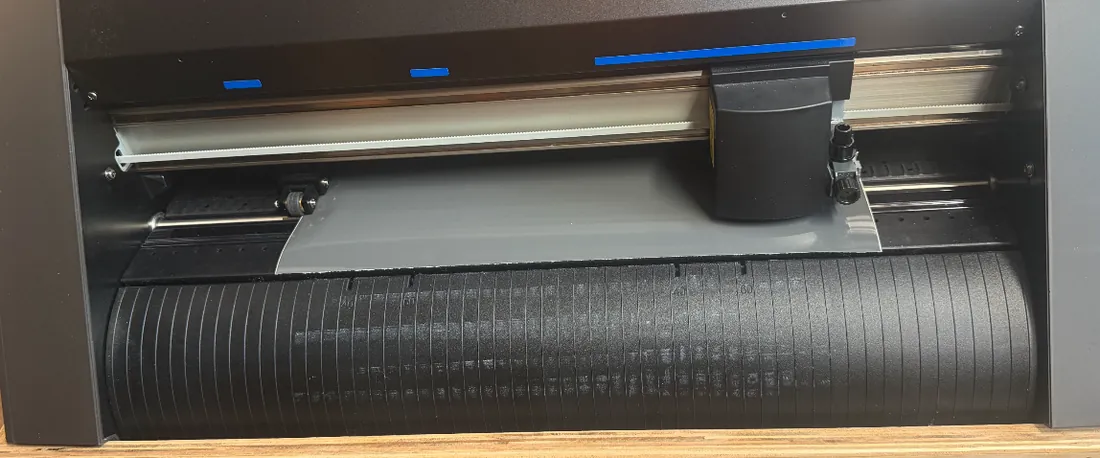
The CE7000-40 feeds material out over a curved front. On our bench the cutter sits behind a raised front edge, with a 7.2 mm gap between the two. Material coming off the platen drapes down the curve into that gap, and catches there when the cutter pulls it back in.
The ledge covers the curve and the gap with a flat top, about 2 mm above the platen, that reaches past the bench's edge. Material slides out onto it, and back.
How it fits
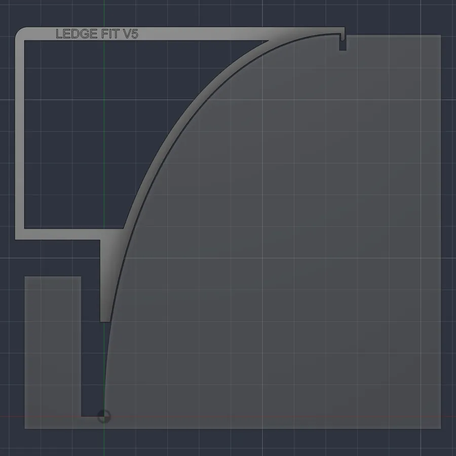
- A notch, 1.3 mm wide, drops into the 2.15 mm slot between the curved front and the platen and holds the ledge in place front to back. Its tip is tapered so it finds the slot.
- The underside follows the curve 0.4 mm clear. We measured the curve at 74.3 mm across and 120.56 mm tall, and drew it as a quarter ellipse.
- A stem reaches 26 mm down into the gap in front of the cutter and stops well short of the floor.
- The top reaches out past the bench's edge, with a 4 mm round on its front so material slides back over it.
- The ledge is hollow, with a 4.25 mm top and walls 3 to 3.6 mm thick.
How it got here
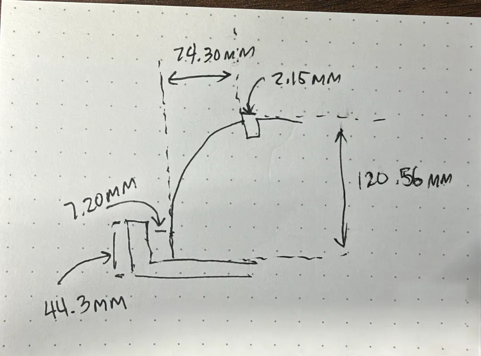
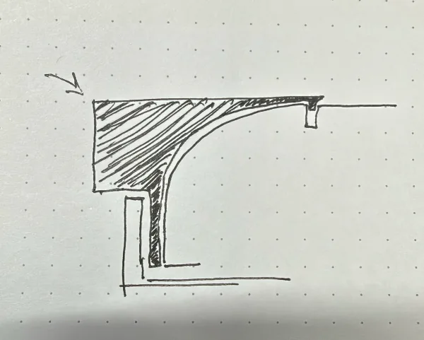
We measured the cutter and the bench with calipers and sketched the profile before drawing anything in CAD. The fit tests are 4 mm slices of that profile. Each prints flat in about 16 minutes and can be tried in the cutter before the whole ledge is printed.
Version 2 was printed and tried. The notch hung on 0.6 mm of plastic, and the block and the stem ran into the bench. From there we marked up the model, and each round of notes made the next version.
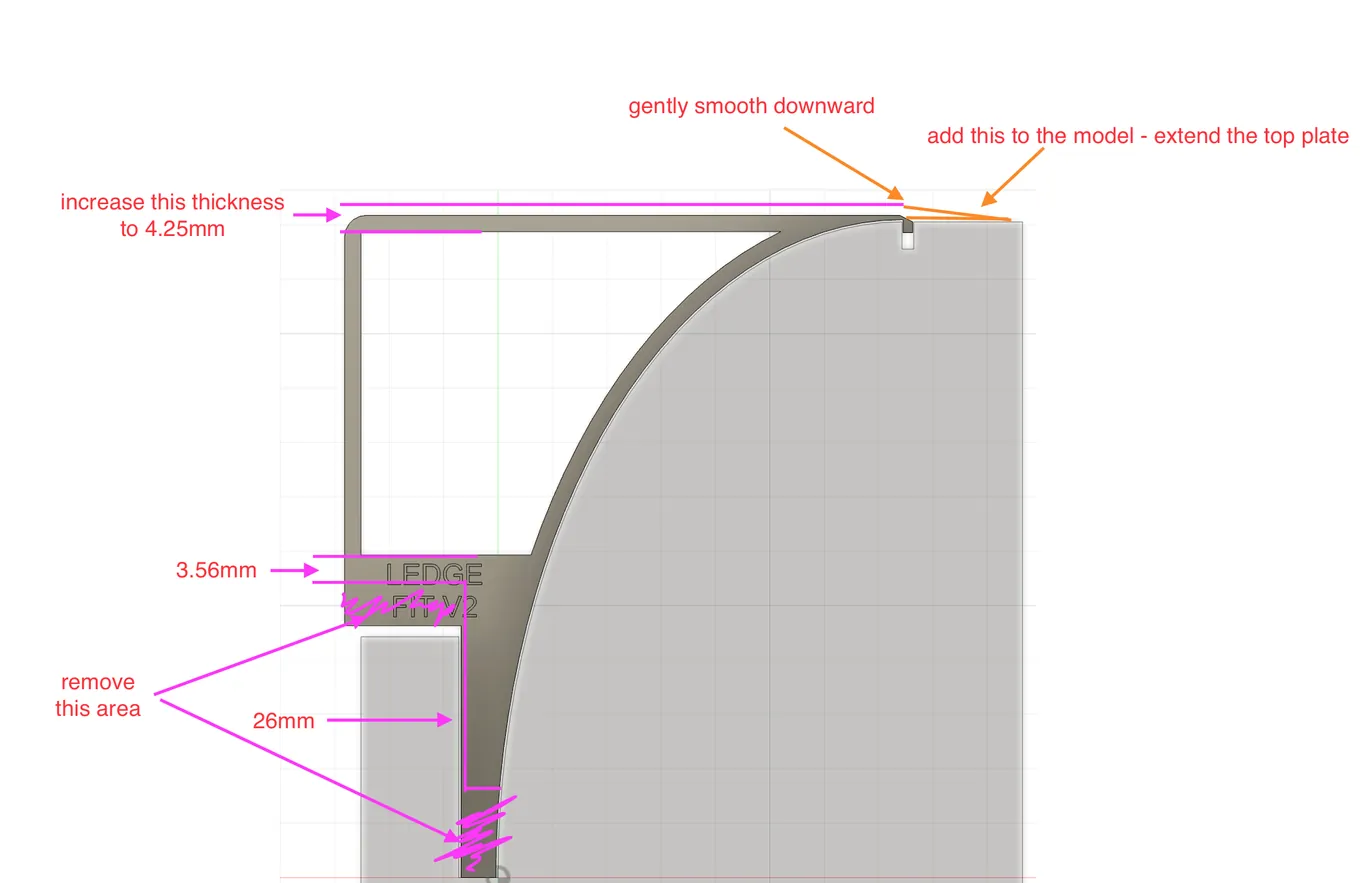
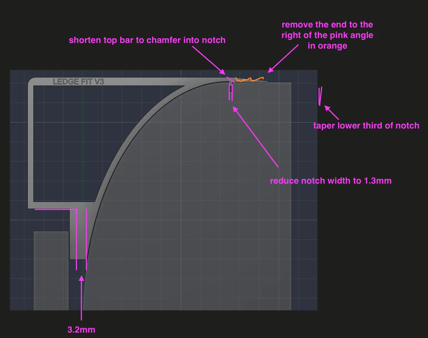
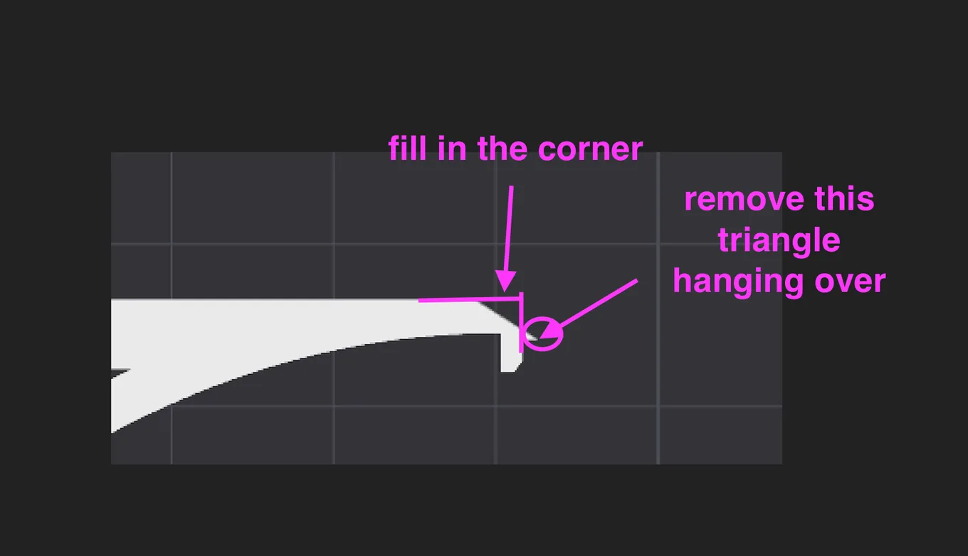
The files here are version 5.
Print it
- Print the fit test first and stand it in the cutter. The notch should drop into the slot, and nothing should touch the bench.
- Then print the ledge standing on its end, the way it opens in the slicer. Every face is upright, so it needs no supports.
- For a wider ledge, print more than one and set them side by side. They are not joined yet.
Before you print
It is fitted to our CE7000-40 on our bench. The notch, the curve and the top follow the cutter. The stem and the block follow our bench, whose front edge stands 7.2 mm in front of the cutter. If yours is different, the fit test will show it in 16 minutes.
Version 5, 26 September 2026